• Enter the April CB750 Supply gift certificate giveaway! It's easy... Click here, post something, and you're entered into the drawing!

regulator 1979 CB750 labeled image

scientist

CB750 Member
Messages
6
Reaction score
0
Points
1
Location
oregon
I'm helping a friend wire up a dune buggy with a 750 motor in it. well tweakers have worked on it prior.. every single wire is practically the wrong color. they had the wires to the points taped up like they were not used. I think I've got everything the way its supposed to be.. but if somebody had an image the regulator with the wires not by color but by what they are, like positive, negative from the rectifier and then regulated + voltage coming out to the battery.. haven't done much work vehicles but i do work on electronics.. I would be much obliged.
 
bike.jpg

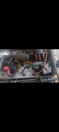
I'm helping a friend wire up a dune buggy with a 750 motor in it. well tweakers have worked on it prior.. every single wire is practically the wrong color. they had the wires to the points taped up like they were not used. I think I've got everything the way its supposed to be.. but if somebody had an image the regulator with the wires not by color but by what they are, like positive, negative from the rectifier and then regulated + voltage coming out to the battery.. haven't done much work vehicles but i do work on electronics.. I would be much obliged. here are some pictures with the drawing that I think maybe partially right.. the engine has five wires three yellow, one white, one green, and what looks like a light green with a red stripe .

three yellow go to the rectifier the white one goes to the first plug on the regulator. green goes to the ground spot on the top of the rectifier. there is a wire on the rectifier that is unhooked, the last plug on the regulator is unhooked, and the light green with the red stripe is unhooked. if I knew what the five wires were to begin with and what each of the wires on the regulator and rectifier do we make more sense to me as i've never worked on motorcycles. can't seem to find a good schematic a lot of the forums at 404 not found on the image .
 

Attachments

  • Screenshot_20230729-234035061.jpg
    Screenshot_20230729-234035061.jpg
    142 KB · Views: 51
thank you kindly surely appreciate the help . i think i have it worked out. the f on the regulator that goes to the field coil that is the output for the regulator? and the first terminal that goes to the battery and the output of the rectifier that's the input for the regulator? I have an understanding of electronics.. but finding a condensed version of what each pin on the regulator is and how it functions is almost impossible.. especially for a 1979 version. looking at this schematic it seems to me that the regulators only job is to provide a regulated voltage to that field coil?.
 
thank you kindly surely appreciate the help . i think i have it worked out. the f on the regulator that goes to the field coil that is the output for the regulator? and the first terminal that goes to the battery and the output of the rectifier that's the input for the regulator? I have an understanding of electronics.. but finding a condensed version of what each pin on the regulator is and how it functions is almost impossible.. especially for a 1979 version. looking at this schematic it seems to me that the regulators only job is to provide a regulated voltage to that field coil?.
I am far from an expert, but a rectifier regulator only has one job: is to regulate and rectify the AC power to charge the battery.
 
this is the closest regulator I can find that matches up with mine mine does not have the white and green sticker.. in the schematic it goes white green black.. that is how I have it wired up. if it's supposed to match the one below then I may have it incorrect. is there a test I can do with a multimeter or scope to test the leads on the regulator?. is the order that they're in pictured below the standard in 1979?. they used reverse polarity protection diodes back then I think.. connecting the wires in the wrong order won't damage it?.. obviously connecting the positive to the ground pin on the regulator would not be good.. cause the wire to smoke... I apologize for my lack of knowledge.. trying to wade through the internet and gather the correct information about this is proving a bit difficult.. if there's a CB750 guide for beginners or idiots I will take no offense to be pointed me in that direction.
 

Attachments

  • Screenshot_20230901-080107063.jpg
    Screenshot_20230901-080107063.jpg
    159.9 KB · Views: 26
I hope somebody chimes in shortly who knows better than I do. Yes, you can test RRs on the bench via static diode tests, and dynamically with the bike running. That's really as far as I can go with your question. Sorry.
 
Unfortunately that regulator you posted a pic of looks nothing like a regulator for a DOHC. On the DOHC bikes the regulator is a square-shaped thing that's all aluminum fins and outputs a green (Honda in most cases green=ground), a red/white which goes to the starter relay/solenoid to charge the battery, and a black which provides power to the switches and lights. See below for a typical DOHC regulator/rectifier unit. Input from the stator is the three yellows, one white, and one black.

First you need to figure out what year that motor is; that'll probably help us out. Please post pics of the motor overall, as well as the engine number.

1693594953021.png
 
Back
Top