RobG
CB750 Enthusiast
Des photographies de vos commutateurs pourraient être très utiles.
Merci beaucoup d'avoir pris le temps de me répondreUne chose à la fois, une chose à la fois
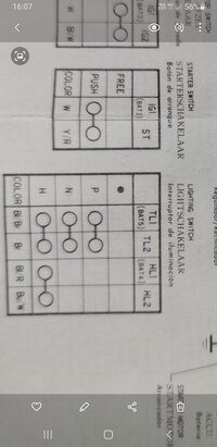
HL1 Celui-ci intègre le fusible pour le démarrage et l'allumage. Pas vraiment de bouton, mais intégré dans une position d'interrupteur. Si l'interrupteur est intact et que tous les connecteurs de vos fils sont corrects, ils se rejoignent tous à l'intérieur de la coque du phare. J'espère que ceci vous aidera.")
 ..j'y vois un peu plus clair même s'il me reste un peu à comprendre pour les autres boutons et abréviations
J'essaie d'envoyer ça au plus vite..merciDes photographies de vos commutateurs pourraient être très utiles.
Mon français est très limité. Mais j'essaie!Merci beaucoup d'avoir pris le temps de me répondre
Mon écriture n'est pas si bonne.Thank you for the answer...i see better but i still to understand the others wire and the other buttons on the left controler ..and sorry for my english tooMon français est très limité. Mais j'essaie!

Thank you it will help me a lotPlus d'information?
...if you have the other part of the right controler too .. 


Bon chance....thx a lot
Hi , thx for helping me, i appreciate but i need your help againBon chance.
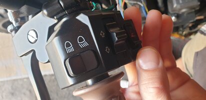
... sorry but electricity is not my thing .. on my left controler i havent the HL1 because i have not the passing switch ...its an universel controler as the right too... so i dont know how to connect the wire and where.
OK thx... if I have other problem i'll ask you if you are ok.. but thx you help me so much..W est le relais clignotant L/R (couleur gris). Le fil de l'interrupteur neutre est vert clair/rouge vers la diode et le module de commande d'allumage. HL1 ? isoler pour l'instant?

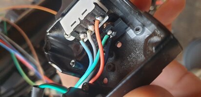
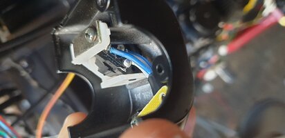
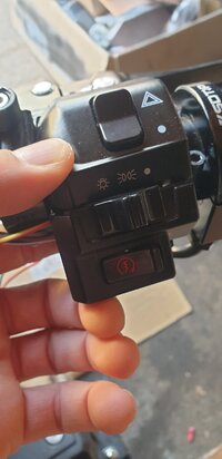
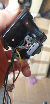
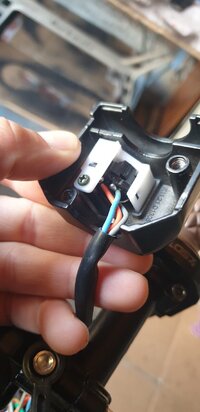
Hi, this is pictures of controlers... on the left controler you can see there's only HI and Lo for the light ...no passing switch...and the turn switch with the orange wire to the left, light blue for the right and the grey but in the neutral ???W is the L/R clignotant relais (gris couleur). Neutral switch wire is light green/red to diode and ignition control module. HL1? isoler pour l'instant?