• Enter the April CB750 Supply gift certificate giveaway! It's easy... Click here, post something, and you're entered into the drawing!

My Wiring Harness Sucks....

Wez_

CB750 Addict
Messages
349
Reaction score
0
Points
16
Location
Enfield, CT
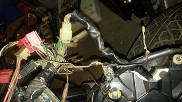
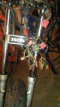
All the pieces are there but it has been hacked at a million times. Ill probably try and find a new harness. What I can repair, I will, and use heat shrink tubing. For now, I want to get comfortable with the harness, be able to clean it up and modify it also as needed. I want to eventually install the motor and see if it fires up and sync the carbs. Tear it back down and style the bike. To do so, Ill need to reconnect some circuits and components electrically at a minimum to get the bike running. Also, it would be a great opportunity to start learning the bikes electrical connections. If anyone has any knowledge of these connections and can shine some light on which ones are needed, or can identify which circuits do what, that would be greatly appreciated. Thanks in advance!

A - Connect
B - Connect
C - Instrument Cluster
D -
E -
F -


Electronics.jpg
I need a key which probably means I'll need a new ignition switch. Also rear harness connections to the battery and a gas tank key....Lots of work still
 
Look up the basic hacked circuit that has been used on choppers before, It's been shown or linked to a couple times before here onsite. Uses only the most basic things to keep bike running.

Or a possible 'Honda DOHC 750 chopper wiring diagram' search on google ought to turn up something.
 
Seems like you haqve a massive project and it does need a huge amount of knowledge, especially on the electrical side to do it. I have resolved to give up on things like rewireing bikes as it is out of my depth and just study the manuals for days try to do it on my cb 750 but don't really get anywhere. Trace each wire, chech the manual, get the multimeter knowledge, it is tough shit.
 
Motorcycles are spit simple compared to a modern electronically controlled car............once you start communicating in canbus part-to-part and sending responses in pulse width modulation it gets plenty crazy.
 
Motorcycles are spit simple compared to a modern electronically controlled car............once you start communicating in canbus part-to-part and sending responses in pulse width modulation it gets plenty crazy.


LOL, can bus communication and pulse width modulated replies...love it! Reminds me of the diode lasers of the pumping unit :)

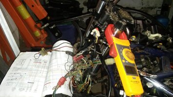
So....I have made some progress but this project will surely take some focus. So I have successfully installed the motor in the frame and connected a battery to the system. I do not have an ignition key also, so I disconnected the connector at the ignition switch and installed a jumper wire between the red and black wires. (more on this later)

Connected the short ground wire to the frame and battery. Short red wire between solenoid and + to the battery. The solenoid harness is connected and all the harness are connected at the front of the motorcycle. Think all that is not connected are the spark plugs, head light, rear light harness and blinkers. Rest seems connected, including instrument cluster, neutral safety switch and clutch switch.

One thing I notice is that when I connect the battery, NO sparking occurs. usually when I connect a battery to a vehicle, the circuit completion usually generates some energy or sparks. There is NO sparking or signs of life in this system.

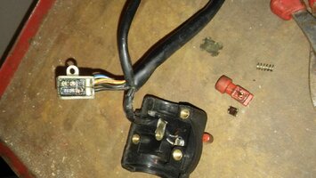
When I try the start switch, nothing happens. If I short the starter solenoid, the starter does crank. Cleaned the heck out the gummed up start switch. (it was heavily corroded) Did a continuity test on the switch and the switch and circuit work properly yet the bike will not crank via the switch. No instrument cluster lights neither. One last observation is that if I keep the positive probe across the positive terminal of the battery, and probe nearly every connector in the harness, I measure 12V nearly everywhere. Does this indicate my harness is potentially shorted? I notice if I move the positive lead of my multi meter across other circuits that I think should have voltage, I tend to measure 0.

I know voltage is the difference in electrical potential between two points, so one point must be + and the other - for a voltage reading to occur. Also 0 Ohms is an ideal resistance as opposed to lets say two connecting points measuring 300 ohms for example.

So hopefully some of you gurus can give me some multi meter measurements of voltage or resistance that I can perform on each component starting at the battery and moving one component at a time along the schematic.

I have multiple color schematics also
20180117_182253.jpg

20180116_182031.jpg

20180115_215410.jpg

20180115_220129.jpg
 
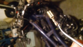
I keep a small tool box with a soldering iron, heat shrink tubing, solder, connectors, wire and all sorts of extras. This wire was repaired nicely. Had to do two repairs so far.


View attachment 8241
 
Being that a harness is the object that sends electricity out to various devices it only makes sense that most wires will show 12V at the end of them since they supply that to the various parts.

FYI, if you have say a 50 strand wire and 45 of those strands are broken or cut off by corrosion you can still get 12V at the end of it but the wire will not carry a load since much of it if broken. Volts do not equal amps in a wire.

So i would expect high resistance or heating up. No?

Great progress though. I had the connector for the solenoid connected to a different harness. They interchange, but don't match electrically. Found that mistake and now almost everything working. I still need an ignition switch and too figure out where one green wire goes
 
Maybe neither. Voltmeter low enough in power it just shows continuity. No heating as the air cannot carry current. Think about switches open to not work. Usually the powered object just simply does not work and you give up before any heating happens.
 
Maybe neither. Voltmeter low enough in power it just shows continuity. No heating as the air cannot carry current. Think about switches open to not work. Usually the powered object just simply does not work and you give up before any heating happens.

I'm proud i found the mistake i made when connecting everything by memory. The color schematic at the back of the book helped tremendously! The colors weren't matching and then i found my mistake. Took like a day of trial and error, studying the schematic, probing and repairing connectors. I think i need to finalize the carbs and keep connecting things up. The air cleaner is terrible.
 
Back
Top